Controllable Pitch Propeller Schematic Operating Systems: (a) push-pull rod system and (b) hub piston system Source: page 22 of Marine Propellers and Propulsion second edition by John Carlton
Also read: Boat Propeller
Raja Ampat islands are beautiful travel destination for visitors who want to enjoy snorkeling, sightseeing, birdwatching and wildlife watching. The archipelago has got the highest marine biodiversity in the world. Its rainforest and coastal areas are the natural habitat of a lot of species of birds and other animals. This is a travel journal of Charles Roring.
Propeller is now the most common form of propelling device for ships and boats। In the Book of Marine Propellers whose author is John Charlton, it is said that propeller is not the only form of marine propulsion system. Propeller predecesors such as paddle, paddle wheel and sail are still being used as marine propulsion systems although their percentage has been far lower then the time when propeller had not been invented.
Voith Schneider propellers was first invented in 1920s by Kirsten-Boeing. Then, it was developed an improved by Voith-Schneider. This kind of propulsion system works on vertical axis with some six to eight vertically mounted vanes rotate on a disc in horizontal plane. Voith Schneider propeller is mostly used in ships or boats that need highly manouvering capabilities. They are passenger boats, tug boat.
Magnetohydrodynamic propeller. The term propeller here should not be associated with the conventional marine screw propeller. Propeller in this propulsion system is simply the terminology for a propulsion device. Magnetohydrodynamic propeller does not have any moving parts in its main propulsor. Water that passes through a duct is accelerated by magnetic coil and electrodes which wraps the duct. Although it has not been a viable propulsion system for commerical uses, this propulsion system has a potential advantage of being able to operate in vibration-free environment. Such property is needed in warships and passenger ships. This propulsion sytem still needs more research before a commercially viable device can be manufactured. Also read: Material and Strength of Marine Screw Propeller and Pitch diameter ratio of a propeller and engine performance of a ship; Ship displacement calculationby Charles Roring in Manokwari of West Papua - Indonesia
The strength and dimensions of a ship's propeller is influenced by various propulsion factors and the material choice. If the resistance and propulsion parameters of a ship has been determined, the next step is determining the propeller dimensions. One of them is the thickness of the blade.
In calculating the thickness of the blade, a propeller designer usually has to perform strength calculation so that he can determine the minimum thickness of the blade at radius 0.2 R of the ship's propeller. The calculation is usually based on Taylor's method which is well explained on pages 288 to 301 of The Design of Marine Screw Propellers written by T.P.O. Brien.
Propeller Materials – The Taylor formulas used in the propeller strength calculation are important in assessing the designed working stress and the safe thickness of propeller blade at 0.2 R. The Classification Societes have provided information about propeller materials and their properties which a naval architect or propeller designer can use to design the required propeler. The following table is the requirements provided by Det Norske Veritas for propeller materials
Propeller Material | Minimum ultimate tensile stress (kg/mm2) | Minimum Elongation (%) |
Cast steel | 41 | 20 |
Special propeller bronze | 45 | 20 |
Ni-Al-bronze | 60 | 16 |
Nodular cast iron, heat treated Not heat treated | 40 | 15 3 |
Special cast iron | 55 | - |
Ordinary cast iron | 24 | - |
Gun metal | 14 | 8 |
The above information is presented on page 285 of The Design of Marine Screw Propellers by T.P.O. Brien. Besides the minimum tensile stress, other propulsion parameters which we need are delivered horse power PD, blade number, RPM, propeller diameter, chord diameter ratio at 0.2 R, material density, and rake of propeller.
The average designed working stress and material density for marine screw propeller is provided below
Material | Density | Design Stress (lbs/inch2) | |||
Single Screw | Twin Screws | ||||
(lb/ft3) | Reciprocating engines | Turbine or diesel electric | Reciprocating engines | Turbine or diesel electric | |
Manganese bronze | 525 | 6000 | 6250 | 6250 | 6500 |
Nickel-Al-Bronze | 480 | 6750 | 7000 | 7000 | 7250 |
Cast iron | 450 | 2500 | 2600 | 2600 | 2700 |
With the development of research and technology in ship's propulsion new materials have been introduced for marine screw propeller. Students and practicing propeller designers must refer to the latest data provided by various classification societies.
Propeller Strength Calculation - For calculating the compressive stress, the following Taylor's formula is usually used:
Then, for calculating the tensile stress of the propeller, the following Taylor's formula should be used
ST = SC (0.666 + S4 t.2/c)
For further explanation of the application of above Taylor's formulas for propeller strength calculation, I suggest that you read T.P.O. Brien's book, The Design of Marine Screw Propellers. The above formulas cannot be used independently. They have to be used with a graph depicting the Strength Criteria of Propeller formulated by Taylor which is given on page 296 of the book.
After performing the strength calculation, the thickness of the propeller is safe for the operation of the ship at the designed speed.
by Charles Roring in Manokwari of West Papua
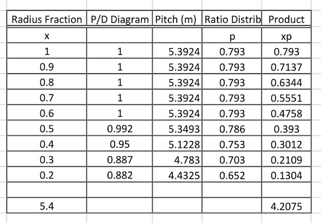
The performance of marine propulsion machinery is much influenced by the propeller installed behind a ship or a boat's hull. If a propeller is well designed, the engine will work well without suffering overloading or underloading. Propeller designer knows that the selection of pitch diameter ratio plays a very important factor.
If the pitch diameter ratio is too high, the main engine will suffer overloading. When the ship is moving on its service speed at sea, the sign of overloading can be seen from its exhaust pipe. A lot of black smoke will be released by the engine whose propeller's pitch diameter ratio is too high. Further inspection to the inside parts of the engine shows that the valves are burnt. Sometimes we can find cracks in the cylinder heads.
If the propeller's pitch diameter ratio is too small, then a sure sign for this is that slow speed of the ship, and cavitation. Cavitation is usuall solved by increasing the developed blade area ratio and diameter of the propeller. We may feel that the fuel consumption is small but in reality the speed of the ship or boat is lower compared to other similar ships.
The solution for too low or too high propeller pitch diameter ratio is repitching. Repitching has to be done by experienced propeller manufacturer with the help of an experienced propeller designer or a naval architect who understands the resistance and propulsion system of ships or boats. Also read: Ship displacement calculation, and The propulsion system of submarine
The propulsion system of a conventional submarine is designed to meet two different operating condition. The first one is when the submarine is moving on the surface of the water and the second one when it is moving under water.
If it is on the surface the resistances it has to overcome are the same as those of conventional surface ships. There will be water (frictional and wave making resistances) and some air resistance. If the submarine is operating under deep water it will not face wave making resistance. Due to greater wetted surface, the submarine will have greater frictional resistance.
Every submarine has been designed and constructed to operate in three dimensions. It can move forward, diving, and manouvering to the right and left sides both on the surface or under water. To have such abilities, a submarine will need not only rudders for moving on horizontal planes but hydroplanes for controlling depth.
When moving on submerged condition, a submarine needs to be fitted with Air Independent Propulsion (AIP). The diesel-electric scheme is the most common form of the submarine propulsion system. Diesel engine will be used to propel the ship if it is on the surface but electrical drive supplied by batteries will be needed to propel the submarine when it moves underwater.
Often submarines need to operate in longer period of time underwater especially when encountering enemies. This operating condition needs highly efficient batteries that can provide greater and longer endurance. In the past, naval architect decided to equip such submarines with nuclear power plant.
Now other alternatives such as closed cycle diesel engines, fuel cells and Stirling engines are being developed. Actually, diesel engine is not an ideal choice for a submarine due to its toxic fumes which can harm the ship crews. Therefore, efforts to improve the efficiency and size of the batteries are now being carried out to increase the overall performance of the propelling system of the submarine. by Charles Roring in Manokwari of West Papua